MIDI Xylophone with Arduino Mega
This project uses an Arduino Mega, relay boards, and solenoids to convert a $30 xylpohone (technically a glockenspeil) into a MIDI output device. The 3D printed parts were designed in Autodesk Fusion 360 and printed on a Prusa MK3s. The laser cut parts were designed in Adobe Illustrator and cut on a Boss laser. MIDI songs are being played on the free LMMS digital audio workstation. LoopMIDI creates a vritural midi port on the laptop to pass the signal from LMMS to Hairless MIDI, which creates a serial bridge to the Arduino Mega over a USB cable.
Motivation
This was an iteration of a project I did a few weeks previously involving a Music Maker lap harp. Most of the technical details between these two projects are the same. The Music Maker also had two octaves, but only in the key of G major, so it was limited in what it could play. I ordered this “xylophone” off Amazon because it had two chromatic octaves and was cheap enough to experiment with.
Process
Most aspect of this project were similar to the Music Maker, just a bit bigger. The stand, the electronics, the number of GPIO pins needed, etc.

The double-decker stand is laser cut plywood. The outline was made in Fusion 360 and cut on a Boss Laser. The corner supports were also designed in Fusion and printed on a Prusa MK3s printer. Some notable differences from the previous project is the inclusion of both a 12V and 5V ACDC switching power supply (the former for the relay boards, and the latter for all the solenoids. Also, two relay modules were needed for all the relays instead of one, even though 7 of them were left unused. Lastly, an Arduino Mega was used in place of an Uno so there would be enough GPIO pins.
Relay Module
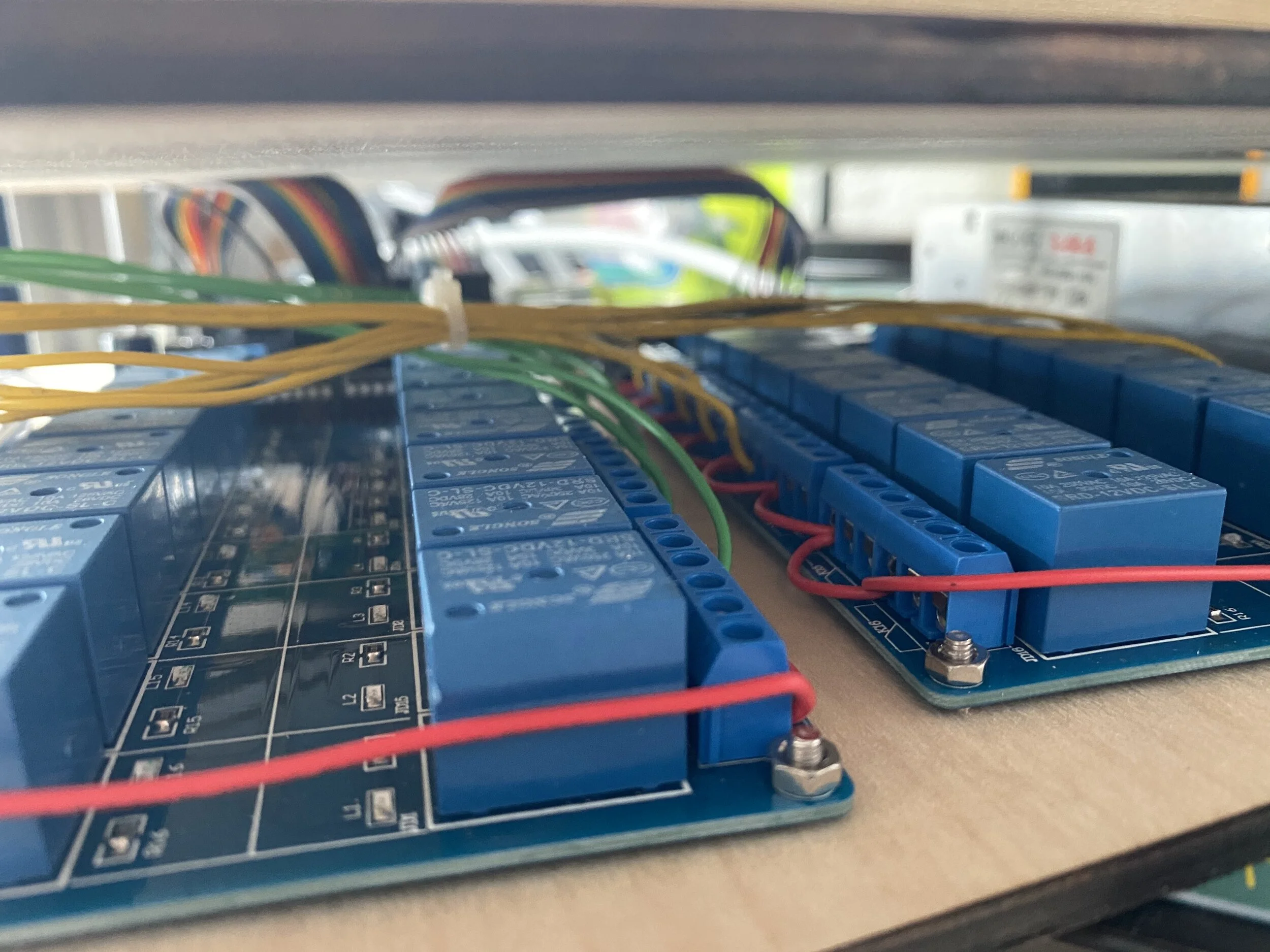
The relay module is made by SainSmart and cost me $15 off Amazon. It has 16 relays that are controlled by 5V logic level. It requires a 12V input to operate, but has 2 pins with regulated 5V output. I originally thought I could use this 5V source to power the solenoids, but the large swings in current running so close to the Arduino and input pins caused all kinds of havoc. Instead I used a separate ACDC switching power supply unit from an old LED project. This meant the Arduino, relay board, and solenoids are all powered by separate sources, creating more cables than I cared for, but solving my performance issues.
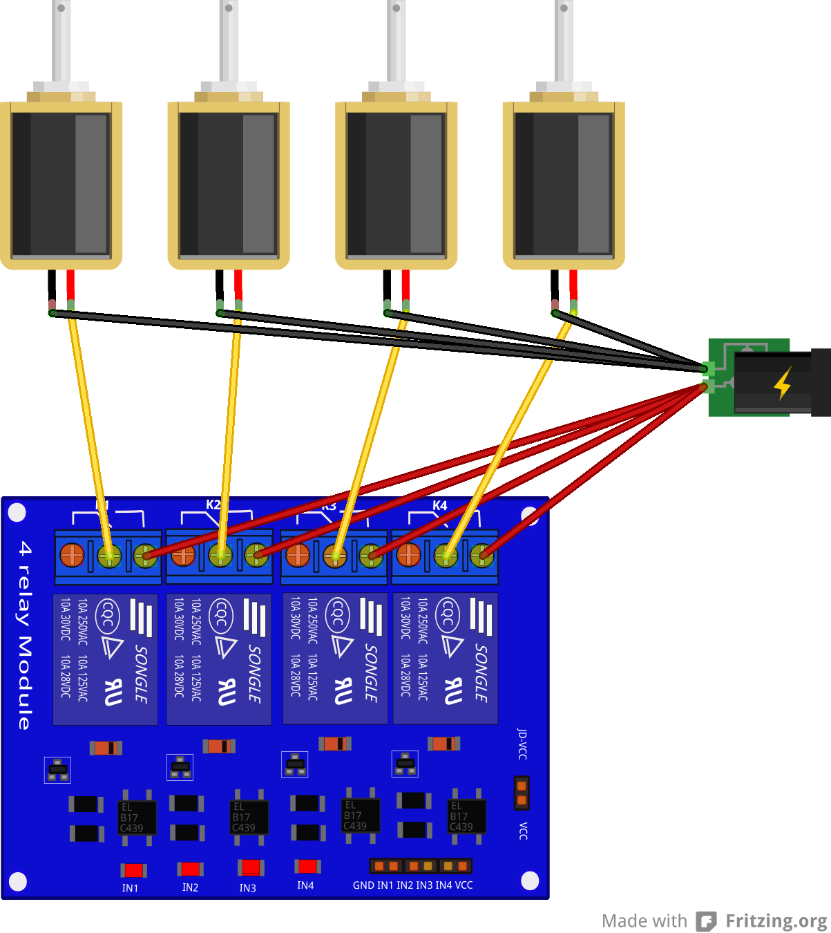
Each of the relays has three connections: the common pin (middle) and the normally-closed (NC) and normally-open (NO). When the relay board is unpowered, or the input pin for that relay is held HIGH, the common pin is connected to NC. I connected all the NO pins of the relays in parallel to the 5V of the power supply and the common pin of each relay to its own solenoid (like in the schematic below, but 4 times as big). The output of the solenoids all returned to the GND of the power supply. I wasn’t sure if it was better to have the solenids constantly held at 5V or the wires running around the relays, but this is what I ended up doing.

Solenoids
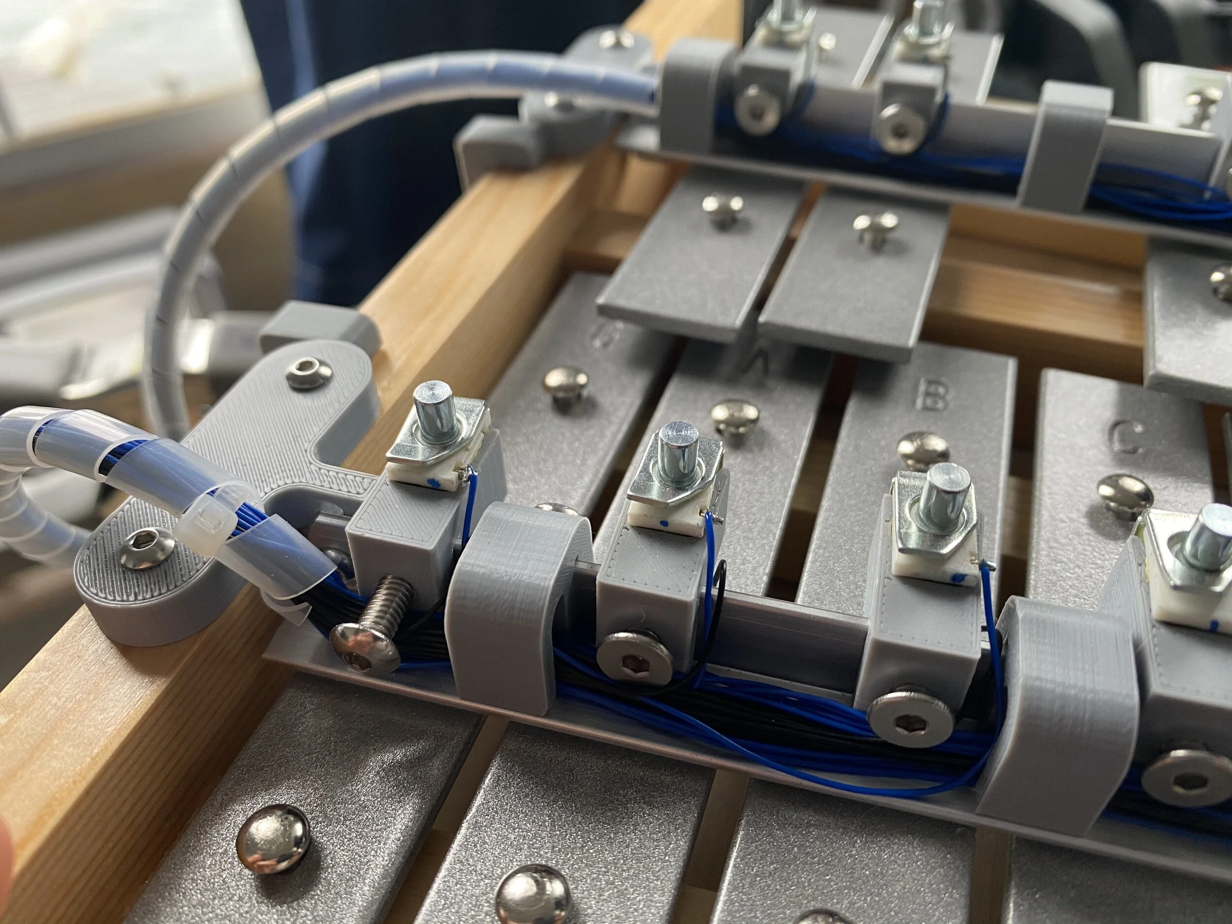
The solenoids I purchased from DigiKey. I wasted a number of them by accidentally snapping their wires by pushing them in to their holders. The spacing between the keys on the instrument varied, so I tried to engineer in ways to adjust the position of the solenoids. First, I designed and 3D printed a bunch of clips that would hold the solenoids by their round bodies, leaving enough room to still solder wires to their small terminals. These clips slipped over a piece of stock angle aluminum bar from Home Depot and they each had a hole that allowed a set screw to hold them in a final position. This took care of lateral adjustability. For vertical adjustability I 3D printed supports for either end of the aluminum basr that included a vertical slot for fine tuning the height.
Files:

Programming
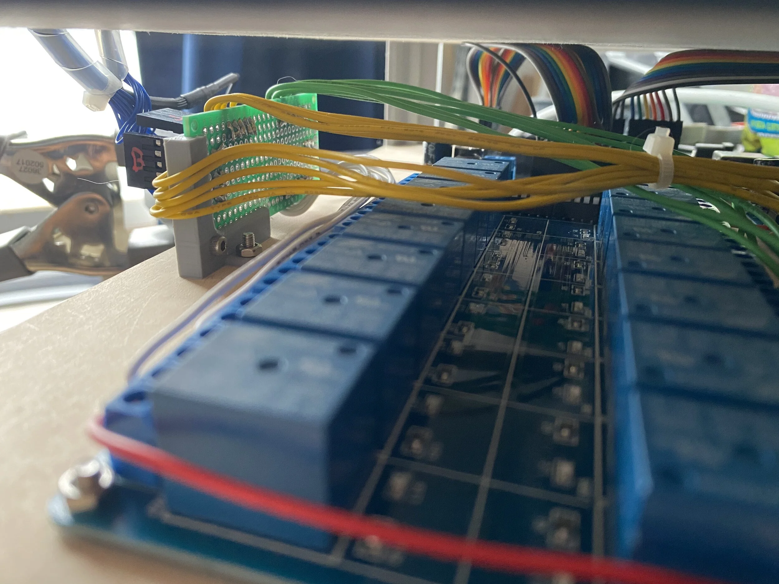
I used 25 of the digital GPIO pins on an Arduino Mega to connect to the input pins on the relay modules. I also connected GND from the Arduino to GND on the relay modules. I did some test runs using simple digitalWrite() commands to test that I hadn’t flubbed any connections or soldering jobs.
To tackle the final challenge of adding midi control, I looked for help online. I found this article about an Arduino Glockenspiel by Mike Cook particularly helpful, even if the article was 12 years old and the project was even older than that!
I’d previously used the MIDIUSB library (that can be downloaded through the Arduino IDE) to make midi output devices (instruments that created midi signals that were then played by a midi synthesizer application on my computer), but for this project I used “MIDI Library,” which can’t be found through the IDE, but can be downloaded from GitHub. The MIDIUSB library works with boards that have native USB capabilities like the Micro and MKRZero, but the MIDI Library can work with an Uno. The MIDI Library also works well with the Hairless MIDI application (see more in Software below).
My code is pretty simple, after all is said and done. The loop() is mostly just a function that reads what is coming over the USB cable. If it reads a ‘note on’ signal it uses some callback functions to determine what note to play, then plays it! I ignore velocity and all other command bytes. Notes received that aren’t on the xylophones are ignored, except those that are within one octave of the highest and lowest note. In that case, the note is transposed one octave so it can still be played on the xylophone (it sounds a little odd, but is better than silence on most songs). I did have some issues where the relays wouldn’t return to their original state after playing a note, so I added that to the loop() as well, which I feared would slow things down, but didn’t have a noticeable impact on the performance in the end.
Software
There are a number of pieces of software I had to install to make everything communicate nicely. First, I needed some software that would generate midi signals. I’ve used Ableton in the past, but wanted something more universal (i.e. free). I downloaded LMMS, which is a free digital audio workstation that works on many platforms. It doesn’t include any soundfonts, so you won’t hear much unless you add some. Free packs exist, but I just used the Microsoft GS Wavetable Synth that is included with Windows for troubleshooting. In LMMS and similar programs you can route the output of the music, either through soundfonts on the local system, or to connected midi devices. On Macs it is simpler to route a midi signal to a connected device, but on a PC you’ll need to install some extra programs to accomplish this.
In order for software programs on a Windows computer to pass midi signals to each other, you need to download something like loopMIDI (by Tobias Erichsen), which creates virtual midi ports on the computer. It is my understanding that Macs have this feature built into the operating system. After installing loopMIDI and creating a virtual port, it should show up in the list of output options in LMMS.
Lastly, what loopMIDI is passing the LMMS signal to is a program called Hairless MIDI, which creates a serial bridge to the Arduino Mega. Their website has some really helpful information, so check it out. The “MIDI in” for Hairless MIDI should be the virtual port you created in loopMIDI. When you play something in LMMS you should see that register in Hairless MIDI, even without a connected device. In the “Serial port” menu of Hairless MIDI, select the connected Arduino. If you unplug the Arduino or try to upload code from the IDE this may cause trouble with Hairless MIDI and you should close and reopen the MIDI bridge with the check box.
Most of the songs that you see playing in the video at the top of this page were freely downloaded .mid files from sites like BitMidi. These can be imported into LMMS and often contain multiple tracks. I ignore things like percussion tracks and individually route the melody and rhythm tracks to loopMIDI.
Code
/*
  MIDI Music Maker (Lap Harp)

  This program runs on an Arduino and listens for midi signals to be sent over the USB cable from a midi instrument or digital audio workstation application.
  When the Arduino recieves a 'note on' byte, it writes the corresponding pin LOW, triggering the connected relay and solenoid.

  Download the required library at http://fortyseveneffects.github.io/arduino_midi_library/index.html
  This is not the same MIDI libraries found in the library manager.

  Circuit: Pins A0 - A3 and 2 - 13 are connected to the inputs of a 16 relay module board.
  GND from the Arduino Uno is connected to ground on the relay module.
  The Arduino is powered by the attached USB cable.
  The relay module is powered by its own 12V ACDC wall adaptor.
  A separate 10A 5V power supply is used for the 15 solenoids.
  GND from the power supply is connected in parallel to the NO terminal of each relay.
  The common of each each relay is connected to its own solenoid.
  The outputs of all the solenoids join together and connect to 5V on the power supply.

  This is based on the MidiUSB example included with the library
  Modified by Johnny Devine 2020

*/

#include <MIDI.h>

MIDI_CREATE_DEFAULT_INSTANCE();

// -----------------------------------------------------------------------------
//Declare and define variables

//Pins numbers on Uno and the note they play (relay pin is second number).  h for high, m for middle, and l for low
//int hG = A0;  //1
//int hFs = 2;  //2
//int hE = 3;   //3
//int hD = 4;   //4
//int hC = 5;   //5
//int hB = 6;   //6
//int hA = 7;   //7
//int mG = 8;   //8
//int mFs = A3; //16
//int mE = A2;  //15
//int mD = A1;  //14
//int mC = 13;  //13
//int mB = 12;  //13
//int mA = 11;  //11
//int lG = 10;  //10

int hG = 23;   //16
int hFs = 4;   //4
int hF = 22;   //15
int hE = 25;   //14
int hDs = 5;   //5
int hD = 24;   //13
int hCs = 6;   //6
int hC = 27; //12
int hB = 26;  //11
int hAs = 7;  //7
int hA = 29;  //10
int mGs = 8;  //8
int mG = 28;   //9
int mFs = 13;   //13
int mF = 37;   //2
int mE = 34;   //3
int mDs = 12;   //12
int mD = 35;   //4
int mCs = 11; //11
int mC = 32;  //5
int mB = 33;  //6
int mAs = 10;  //10
int mA = 30;  //7
int lGs = 10;  //10
int lG = 31;  //8

//There are 128 notes in MIDI.  43 is the low G on the Music Maker
//Midi for lG (or G2, I think) starts on 43 and goes to 67 for hG (or G4)
int baseNote = 43;

//Notes in G major that are present on the Music Maker: G, A, B, C, D, E, F#, G
//The first octive would be the midi notes:             43,45,47,48,50,52,54, 55

//This is the array of notes that can be played on the Music Maker.  The zeros are for notes not present on the Music Maker and will be skipped.
int noteList[] = {lG,lGs,mA,mAs,mB,mC,mCs,mD,mDs,mE,mF,mFs,mG,mGs,hA,hAs,hB,hC,hCs,hD,hDs,hE,hF,hFs,hG};

// -----------------------------------------------------------------------------

//Define what action to take when a 'note on' byte is received
void handleNoteOn(byte inChannel, byte inNumber, byte inVelocity)
{
  byte stringnote = noteList[inNumber - baseNote];
  pluck(stringnote,8);
  //In setup() we are only listening to channel 1, so that info is not used here.  Neither is velocity, since that is defined as a constant in pluck()
}


void pluck(int stringnote, int velocity)
{
  digitalWrite(stringnote,LOW);
  delay(velocity);  //set to a constant 8ms above, which seems to sound nice on the Music Maker strings.
  digitalWrite(stringnote,HIGH);
}

// -----------------------------------------------------------------------------

void setup()
{
  pinMode(hG,OUTPUT);
  pinMode(hFs,OUTPUT);
  pinMode(hF,OUTPUT);
  pinMode(hE,OUTPUT);
  pinMode(hDs,OUTPUT);
  pinMode(hD,OUTPUT);
  pinMode(hCs,OUTPUT);
  pinMode(hC,OUTPUT);
  pinMode(hB,OUTPUT);
  pinMode(hAs,OUTPUT);
  pinMode(hA,OUTPUT);
  pinMode(mGs,OUTPUT);
  pinMode(mG,OUTPUT);
  pinMode(mFs,OUTPUT);
  pinMode(mF,OUTPUT);
  pinMode(mE,OUTPUT);
  pinMode(mDs,OUTPUT);
  pinMode(mD,OUTPUT);
  pinMode(mCs,OUTPUT);
  pinMode(mC,OUTPUT);
  pinMode(mB,OUTPUT);
  pinMode(mAs,OUTPUT);
  pinMode(mA,OUTPUT);
  pinMode(lGs,OUTPUT);
  pinMode(lG,OUTPUT);

  //On the relay module, HIGH is the NC closed state of the relays
  digitalWrite(hG,HIGH);
  digitalWrite(hFs,HIGH);
  digitalWrite(hF,HIGH);
  digitalWrite(hE,HIGH);
  digitalWrite(hDs,HIGH);
  digitalWrite(hD,HIGH);
  digitalWrite(hCs,HIGH);
  digitalWrite(hC,HIGH);
  digitalWrite(hB,HIGH);
  digitalWrite(hAs,HIGH);
  digitalWrite(hA,HIGH);
  digitalWrite(mGs,HIGH);
  digitalWrite(mG,HIGH);
  digitalWrite(mFs,HIGH);
  digitalWrite(mF,HIGH);
  digitalWrite(mE,HIGH);
  digitalWrite(mDs,HIGH);
  digitalWrite(mD,HIGH);
  digitalWrite(mCs,HIGH);
  digitalWrite(mC,HIGH);
  digitalWrite(mB,HIGH);
  digitalWrite(mAs,HIGH);
  digitalWrite(mA,HIGH);
  digitalWrite(lGs,HIGH);
  digitalWrite(lG,HIGH);

  MIDI.begin();           // Launch MIDI, by default listening to channel 1.

  //Defines what to do when a 'note one' byte is detected during the read in the main loop
  MIDI.setHandleNoteOn(handleNoteOn);

  //Note the higher baud rate than is often used (9600)
  Serial.begin(115200);

}

void loop()
{

  MIDI.read();

  //Some relays were not being written back HIGH at the end of pluck, putting the soelnoids at risk of being burned out.
  //I was afraid these digitalWrites() would destroy the latency, but it still seems to move quickly enough.
  digitalWrite(hG,HIGH);
  digitalWrite(hFs,HIGH);
  digitalWrite(hF,HIGH);
  digitalWrite(hE,HIGH);
  digitalWrite(hDs,HIGH);
  digitalWrite(hD,HIGH);
  digitalWrite(hCs,HIGH);
  digitalWrite(hC,HIGH);
  digitalWrite(hB,HIGH);
  digitalWrite(hAs,HIGH);
  digitalWrite(hA,HIGH);
  digitalWrite(mGs,HIGH);
  digitalWrite(mG,HIGH);
  digitalWrite(mFs,HIGH);
  digitalWrite(mF,HIGH);
  digitalWrite(mE,HIGH);
  digitalWrite(mDs,HIGH);
  digitalWrite(mD,HIGH);
  digitalWrite(mCs,HIGH);
  digitalWrite(mC,HIGH);
  digitalWrite(mB,HIGH);
  digitalWrite(mAs,HIGH);
  digitalWrite(mA,HIGH);
  digitalWrite(lGs,HIGH);
  digitalWrite(lG,HIGH);

}